
For all of us dealing with the effects of the corona virus, not all aspects of the social lock-downs are bad, as explained in Sandy’s article on keel bolt replacements on his sail boat. As the former VP for Technical Activities, Sandy provides quite an educational discussion for those society members who enjoy sailing their boats on the world’s oceans.
Albert J. Williams 3rd, IEEE Life Fellow
Woods Hole Oceanographic Institution
Woods Hole, MA 02543 USA
awilliams@whoi.edu
Abstract— Social Distancing and closure of Woods Hole Oceanographic Institution (WHOI) imposed restrictions on many of us professionally but I had a project that kept me fully engaged at home. This is a tale of the keel bolt replacement on my sailboat, Shadowfax, in 2020.
I. Introduction
When my wife, Izzie, and I returned from Borneo on March 21, a pre OCEANS Singapore trip cut short by Malaysian flight restrictions, we immediately went into self-quarantine at home in Woods Hole. But I was engaged in preparing my 30’ sailboat for launch on April 30, the latest date permitted at our boatyard for a boat not kept there. Being trapped at home was just what I needed. This was the year for replacing my keel bolts; did them in 1980, 1997, and now it was a little overdue in 2020.
II. Keel Bolts
A. Old Bolts
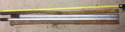
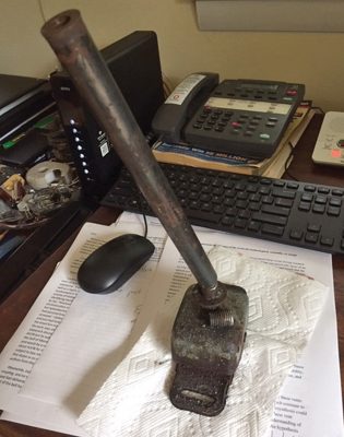
Two of the four old keel bolts were driven out. I had made replacements and had them hot dip galvanized before leaving for Borneo. Two bolts are 42” long and the other two are 38” long, 7/8” in diameter, and each went through wooden floors, about 12” of dead wood, and about 18” of cast iron ballast keel. Fig. 1 shows two new ones and two old ones that did come out. The lower end (right) has been upset by mushrooming them while red hot after excess was cut off and then the bolt was drawn up into a socket in the cast iron with a nut at the top. The socket had been filled with epoxy before bottom paint had been applied.
- Two new hot dipped galvanized 7/8″ keel bolts with old (23 year) keel bolts driven out, cut off when they reached the ground beneath the supported boat, and stacked next to the new bolts ready to replace the next two old bolts when they are driven out. The hex nut is on the top (left) of bolt #4 to illustrate its length compared to the 38” bolt similar to the one that has replaced it. Bolt #3 is 42” and was replaced by a similar one to the longer bolt ready to replace bolt #2. It was expected that the shorter one would replace bolt #1.
B. Pile Driving
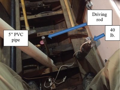
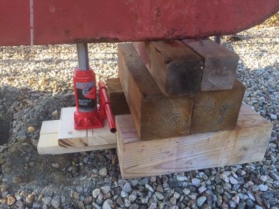
I knew that it took a heavy hammer to drive the old keel bolts out and in 1997 I set up a pile driver with 5” diameter PVC pipe, 5’ long, into which I initially dropped a 20 lb. steel weight. The eventual arrangement is shown in Fig. 2. But bolt #1 and bolt #2 stopped moving after only about 1 3/8” when driven down by pile driving with a 20 lb. weight dropped 5’ repeatedly onto a driver resting on the bolt. Thinking the lower end might be hitting the blocking under the keel, new blocking was acquired along with a 6 ton hydraulic jack and the boat was lifted and the original blocking replaced by new blocking farther aft shown in Fig. 3. But even with the mushroomed heads exposed up in the socket, there was no movement. Over the next six weeks various approaches were tried. On the principal that if it doesn’t work, use a bigger hammer, I acquired a second 20 lb. weight and taped the two together to make a 40 lb. driving weight, the one shown in Fig. 2. No improvement. The characteristic was that the bounce of the weight off the rod was elastic until movement started and then became inelastic and the bounce stopped. But it didn’t stop. A long 1/2” bolt was tapped into the bottom of keel bolt #1 and with a jack and 4’ lever an attempt was made to pull it out. Oil was run into the bolt hole. It was clear that something must be resting on top of the cast iron keel, possibly a splinter of iron from the keel bolt. There was no progress.
- The driving rod extending up from the floor is being driven by the steel 40 lb. weight (right) dropped through the PVC pipe which is placed over the rod. The weight is picked up and dropped through the pipe. When the driving rod is about to disappear below the top of the floor, a longer driving rod is substituted until at the end, after the driven keel bolt has been cut off to permit continued driving, the last piece of bolt falls out and the new bolt, well-greased, is driven into the hole.
C. A Window into the Deadwood
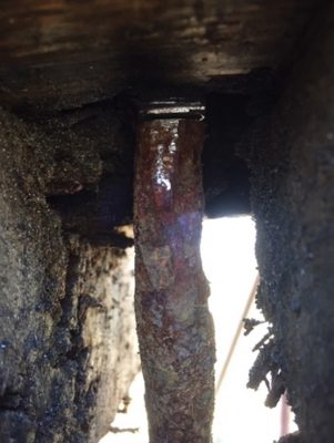
Finally a window was cut into the deadwood where the distortion of bolts #1 and #2 was revealed. The sections of distorted bolt were removed by sawing as shown in Fig. 4 with the bright cut at the top and a cut at the bottom.
- Because the blocking supporting the boat covered the sockets for keel bolts #1 and #2, it was necessary to move the supports farther aft. A six ton hydraulic jack lifted the boat so that a new stack of blocking could be installed and the original stack removed. However, there had been no movement of the lower ends of bolts #1 and #2.
- Deadwood was plunge-cut away to reveal the region where the keel bolt was distorted. Then the bolt was cut at the top and bottom of the window with the plunge cutter and removed.
D. Extracting the Top Section
The top end of the bolt was tapped for a 1/2” bolt and the keel bolt was drawn up and out with the jack and lever as shown in Fig. 5.
E. Driving out the Bottom Section
A high strength steel 3/4” rod was used to drive the lower piece out the bottom.
F. Filling the Window in the Deadwood
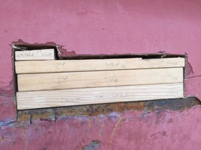
Finally the window was filled with pieces of fir cut to fit and epoxied in around the replacement bolts as shown in fig. 6. .
- A ½”.bolt was drilled and tapped into the top of the #2 keel bolt and drawn up and out with a 4’ steel channel and hydraulic jack.
- Pieces of fir were cut and shaped to fill the window in the deadwood and after the new bolts were in place, these pieces were bedded in place with thickened epoxy.
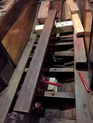
Fig. 5. A ½”.bolt was drilled and tapped into the top of the #2 keel bolt and drawn up and out with a 4’ steel channel and hydraulic jack.
III. Secondary Consequences of Keel Bolt Replacement
A. Floor Damage
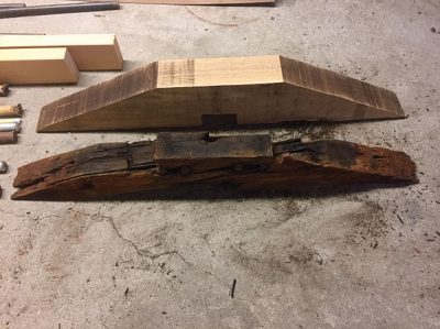
Driving the keel bolts with short rods, and then longer rods, using 20 lb. weight and then 40 lb. weight took a toll on the wooden floors supporting the keel bolts. During keel bolt replacement in 1997 two of the floors showed damage on their aft surfaces and 3”x3”x1/4” steel angles were hot dip galvanized and bolted to the floors to strengthen them and provide a surface for the nuts of the keel bolts to rest upon. In this new replacement, the floor for keel bolt #2 became so damaged that it required replacement as well. I had a large piece of American white oak remaining from a mast step replacement project five years ago and this provided material for a new floor as shown in Fig 7.
- White oak replacement floor above and damaged floor below that it was copied from. Width exceeded available opening so the wings were drilled for carriage bolts and then cut for assembly after insertion in the bilge.
Access under the interior finished work was limited by fresh water tanks on either side so that the wings of the new floor had to be cut and assembled in parts under the finished work. Carriage bolt holes were drilled before cutting so that the wings could be bolted on under edges of the sole. This is shown dry assembled in Fig. 8.
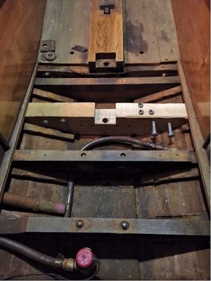
- New floor for keel bolt #2 before the old steel angle was attached. Diagonal cuts to the wings permitted insertion beneath the sides of the sole and under the coverings of the fresh water tanks. The floor was bedded in 3M5200 High Strength Adhesive Sealant and screwed from the outside with #12 silicon bronze wood screws. The external screw holes were plugged with ½” mahogany bungs.
B. Floor for Keel Bolt #4
Keel bolt #4 passes through the floor that also supports the engine bearers and this floor also saw extensive damage from the keel bolt driving. The extent of the damage was only realized as the nut was tightened after the lower end of the bolt was upset and drawn back into the socket in the ballast keel. A remainder of the 3”x3”x1/4” steel angle provided a 12” piece that was machined for the keel bolt and placed under the nut. This has allowed the nut to be torqued down to 300 ft. lb. as for the others without continuing to bury itself into the floor. Replacing this floor will be a major job because it holds the engine bearers and the engine will need to be removed to replace it. Perhaps it will be on the agenda for the next keel bolt replacement in 2040.
While the engine ran fine when the boat was launched and produced expected speed through the water and expected maximum engine rpms at full throttle, there was a certain irregularity to the sound. But it was only on the third excursion that something serious happened. After throttling back the engine to await the raising of the drawbridge for our access to Eel Pond, Woods Hole, where we keep the boat, there was a load clattering and inspection showed the starboard engine bearer moving.
C. Propeller Shaft Coupling
With so much work on the keel bolt replacement and damage to floors, it is advised to check alignment of the propeller shaft coupling but this is a very hard place to see. There is a hand hole in the inboard side of the aft starboard bunk and a place to get another hand in beneath the aft end of the inboard berth panel, but it is hard to see and even harder to work on the coupling. However, inspection showed that one of the bolts holding the coupling together had sheared off and the remaining three bolts were only finger tight after removing the wire preventing them from unscrewing. Separating the coupling revealed a misalignment of about 5° and a small vertical misalignment. These should be adjusted with the four vibration isolating engine mounts. My three cylinder diesel engine is expected to produce more vibration than the four cylinder gasoline engine it replaced so the vibration isolating mounts are required.
D. Engine Mounts
In order to remove the 5° misalignment the forward engine mounts had to be raised about 1” which required moving the aluminum angle brackets and re-drilling the bolt holes connecting them to the wooden engine bearers. This was done and while at it, a 15” section of 3”x3”x1/4” bridged the space between the port and starboard engine bearers tied to the forward engine mount bolts. This last removed the possible motion of the starboard wooden engine mount where apparently the bracket connecting it to the floor timber had failed. But raising the forward end of the engine while making the two halves of the coupling parallel increased the vertical offset and the aft engine mounts needed adjustment. The jam nuts on these could not be moved.
E. Driving Out Frozen Engine Mount
Access to the aft end of the engine is obtained by removing the cockpit footwell liner, a moderately difficult task but it was done without damage. This allowed removal of the starboard vibration isolating mount where at home the jam nut was loosened with a long wrench. But the port mount could not be removed despite taking off the top jam nut. And application of Kroil, guaranteed to free stuck metal parts, failed to improve the situation in 9 days of repeated application. So the top part of the stud was sawed off with my plunge cutter (three days) and then a 3/8” hole was drilled into the 5/8” stud stuck in the unthreaded clearance hole. Finally a 3/8” drift was machined from one of the keel bolt driving rods. Hammering on this drift was commenced with the target of 1000 blows to drive the stud out. First day had 300 blows with a rest after each 100. The second day picked up with the 400 series but on blow 474 there was a thunk. This was the mount falling into the bilge. Fig. 9 is the mount with the drift and the top of the stud that was sawed off.
- The mount that was hammered out on the 474th blow. The drift is in the 3/8” drilled hole and the top of the stud sawed off is beside the drift on top of the vibration damper.
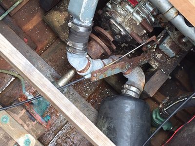
The replacement mount I had ordered had been delivered and it easily went in the hole and was adjusted to remove the vertical misalignment. One more adjustment of all four mounts got the halves both parallel and vertically aligned and new coupling bolts were inserted, torqued down, and wired through their nuts to prevent unscrewing. Fig. 10 shows the aft end of the engine with limited working space between the exhaust pipe, the heat exchanger, and the transmission.
- The coupling is open and above the exhaust pipe. The propeller shaft enters the shaft log through a green shaft seal that is lubricated by grease in the copper tubing entering the seal from the left. The shift cable bracket has been detached to allow more swinging room for the wrench on the jam nut of the starboard mount, which has the top nut removed exposing the 5/8” stud just beneath the heat exchanger at upper right. Lower right is the starboard drain hose from the cockpit liner. The diagonal wooden beam supports the cockpit liner and provides a seat for working on the mounts. The black object at the bottom is the Hydro Hush muffler.
IV. Conclusion
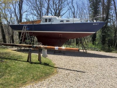
Shadowfax was launched April 30, all painted and ready to sail as in Fig. 11. The post launch work on the coupling and the engine mounts has displaced most sailing and allowed growth to somewhat slow the boat. Full throttle now gives 6.0 knots and maximum of 3300 rpm. But most important is that leak rates are less than any time in the last 20 years.
- Painted and ready for launch on April 30, 2020 as required.
 Suleman Mazhar has been working as a professor in Information & Communication Engineering at Harbin Engineering University (China) since July 2019. He did PhD from Tokyo University (Japan) and postdoctorate from Georgetown University (Washington DC, USA). He had BS-CS from FAST-NUCES (Lahore) and MS from GIK Institute (Pakistan). He is TYSP young scientist fellow (Ministry of Science & Technology China) and have won several research grants from international organizations such as DAAD (Germany), ICIMOD (Nepal), NRPU (Higher Education Commission Pakistan), WWF (Worldwide Fund for Nature) Pakistan. His research focus is deep learning and signal processing applications for environmental monitoring, with particular focus on underwater acoustics, and marine mammal conservation. He is a reviewer for professional journals such as Journal of Acoustical Society (America), IEEE Journal of Oceanic Engineering, IEEE Sensors Journal, Applied Acoustics, IEEE Transactions on Intelligent Transportation Systems.
 Peng Ren is a full professor with the College of Oceanography and Space Informatics, China University of Petroleum (East China). He is the director of Qingdao International Research Center for Intelligent Forecast and Detection of Oceanic Catastrophes. He received the K. M. Scott Prize from the University of York, the Natural Science award (first rank) from China Institute of Electronics, and the Eduardo Caianiello Best Student Paper Award from 18th International Conference on Image Analysis and Processing as one co-author. He has served as an associate editor of IEEE Transactions on Geoscience and Remote Sensing.
 Mohd Rizal Arshad is a full professor at the School of Electrical and Electronic Engineering at Universiti Sains Malaysia (USM), Malaysia, where he specializes in ocean robotics technology and intelligent system. He received his B.Eng. in Medical Electronics & Instrumentation and PhD in Electronic Engineering from University of Liverpool, UK in 1994 and 1999, respectively. He completed his MSc. in Electronic Control Engineering from the University of Salford, UK in Dec 1995. He has supervised many postgraduate students and published extensively in local and international publications. He is a senior member of the IEEE, and was awarded IEEE OES Presidential Award in 2019.
 Itzik Klein is an Assistant Professor, heading the Autonomous Navigation and Sensor Fusion Lab, at the Charney School of Marine Sciences, Hatter Department of Marine Technologies, University of Haifa. He is an IEEE Senior Member and a member of the IEEE Journal of Indoor and Seamless Positioning and Navigation (J-ISPIN) Editorial Board. Prior to joining the University of Haifa, he worked at leading companies in Israel on navigation topics for more than 15 years. He has a wide range of experience in navigation systems and sensor fusion from both industry and academic perspectives. His research interests lie in the intersection of artificial intelligence with inertial sensing, sensor fusion, and autonomous underwater vehicles.
 John R. Potter (IEEE M’94, SM’02, F’18) graduated in the previous century with a joint honours Mathematics and Physics Degree from Bristol and a PhD. in Glaciology and Oceanography from Cambridge, UK studying Antarctic ice mass balance, where he spent four consecutive summers. This work helped underscore the non-linear fragility of polar ice to climate change and led to him receiving the Polar Medal from Queen Elizabeth II in 1988.
 Nick is a Visiting Fellow at the UK National Oceanographic Center, Southampton His nomination was endorsed by the Underwater Acoustics Technology Committee. He had worked as a Research Associate and Lecturer at University of Birmingham and has been working as a Research Scientist at the Applied Research Laboratory, University of Texas, Austin. He has also served as a Program Officer at the Office of Naval Research Global. He is a senior member of IEEE (OES) and a Fellow of Acoustical Society of America (ASA). Nick has also been serving as Assoc. Editor for IEEE JoE and JASA. He is widely acknowledged for his expertise are seabed acoustics, parametric array modeling, sonar beamformer, underwater signal processing.
 Maurizio Migliaccio (M’91-SM’00-F’17) is Full professor of Electromagnetics at Università di Napoli Parthenope (Italy) and was Affiliated Full Professor at NOVA Southeastern University, Fort Lauderdale, FL (USA). He has been teaching Microwave Remote Sensing since 1994. He was visiting scientist at Deutsche Forschungsanstalt fur Lüft und Raumfahrt (DLR), Oberpfaffenhofen, Germany. He was member of the Italian Space Agency (ASI) scientific committee. He was member of the ASI CosmoSkyMed second generation panel. He was e-geos AdCom member. He was Italian delegate of the ESA PB-EO board. He was Member of South Africa Expert Review Panel for Space Exploration. He serves as reviewer for the UE, Italian Research Ministry (MIUR), NCST, Kazakhstan and Hong Kong Research board. He lectured in USA, Canada, Brazil, China, Hong Kong, Germany, Spain, Czech Republic, Switzerland and Italy. He was Italian delegate at UE COST SMOS Mode Action. He is listed in the Italian Top Scientists. He is an IEEE Trans. Geoscience and Remote Sensing AE, International Journal of Remote Sensing AE, and was IEEE Journal of Oceanic Engineering AE Special Issue on Radar for Marine and Maritime Remote Sensing, IEEE JSTARS AE of the Special Issue on CosmoSKyMed, Member of the Indian Journal of Radio & Space Physics Editorial board. His main current scientific interests cover SAR sea oil slick and man-made target monitoring, remote sensing for marine and coastal applications, remote sensing for agriculture monitoring, polarimetry, inverse problems for resolution enhancement, reverberating chambers. He published about 160 peer-reviewed journal papers on remote sensing and applied electromagnetics.
 He has developed various types of Autonomous Underwater Vehicles (AUVs) and related application technologies including navigation methods, a new sensing method using a chemical sensor, precise seafloor mapping methods, a precise seabed positioning system with a resolution of a few centimeters, a new sensing system of the thickness of cobalt-rich crust; and more. He has shown, by using these technologies that AUVs are practicable and valuable tools for deep-sea exploration.
 Donna Kocak has had an outstanding career in defense and scientific projects developing and applying solutions in subsea optics, imaging and robotics. She graduated with an M.Sc in Computer Science in 1997 from the University of Central Florida; an MBA in 2008 from the University of Florida; and M.Sc in Industrial Engineering in 2011 from the University of Central Florida. She is currently a Senior Scientist, Advanced Concepts Engineering, and Fellow at the Harris Corporation in Melbourne, Florida, where she has developed novel optical imaging and communication solutions for under-sea defense and scientific projects. Prior to 2008 Donna Kocak was Founder and President of Green Sky Imaging, LLC (GSI) who developed laser/video photogrammetry software for underwater inspection and survey. Her earlier career positions were with Naval Training Systems Center, Florida; Harbor Branch Oceanographic Institution, Florida; eMerge Interactive; and the Advanced Technologies Group in Florida.
 John Potter has a Joint Honours degree in Mathematics and Physics from Bristol University in the UK and a PhD in Glaciology and Oceanography from the University of Cambridge on research in the Antarctic, for which he was awarded the Polar Medal in 1988. John has worked on polar oceanography, underwater acoustics, ambient noise (including imaging), marine mammals, communications, IoUT, autonomous vehicles and strategic development. He has 40 years’ international experience working at the British Antarctic Survey in the UK, NATO in Italy, SIO in California, NUS in Singapore and most recently at NTNU in Norway. John is a Fellow of the IEEE and MTS, an Associate Editor for the IEEE Journal of Oceanic Engineering, IEEE OES Distinguished Lecturer, PADI Master Scuba Diver Trainer & an International Fellow of the Explorer’s Club.
 Dr. James V. Candy is the Chief Scientist for Engineering and former Director of the Center for Advanced Signal & Image Sciences at the University of California, Lawrence Livermore National Laboratory. Dr. Candy received a commission in the USAF in 1967 and was a Systems Engineer/Test Director from 1967 to 1971. He has been a Researcher at the Lawrence Livermore National Laboratory since 1976 holding various positions including that of Project Engineer for Signal Processing and Thrust Area Leader for Signal and Control Engineering. Educationally, he received his B.S.E.E. degree from the University of Cincinnati and his M.S.E. and Ph.D. degrees in Electrical Engineering from the University of Florida, Gainesville. He is a registered Control System Engineer in the state of California. He has been an Adjunct Professor at San Francisco State University, University of Santa Clara, and UC Berkeley, Extension teaching graduate courses in signal and image processing. He is an Adjunct Full-Professor at the University of California, Santa Barbara. Dr. Candy is a Fellow of the IEEE and a Fellow of the Acoustical Society of America (ASA) and elected as a Life Member (Fellow) at the University of Cambridge (Clare Hall College). He is a member of Eta Kappa Nu and Phi Kappa Phi honorary societies. He was elected as a Distinguished Alumnus by the University of Cincinnati. Dr. Candy received the IEEE Distinguished Technical Achievement Award for the “development of model-based signal processing in ocean acoustics.” Dr. Candy was selected as a IEEE Distinguished Lecturer for oceanic signal processing as well as presenting an IEEE tutorial on advanced signal processing available through their video website courses. He was nominated for the prestigious Edward Teller Fellowship at Lawrence Livermore National Laboratory. Dr. Candy was awarded the Interdisciplinary Helmholtz-Rayleigh Silver Medal in Signal Processing/Underwater Acoustics by the Acoustical Society of America for his technical contributions. He has published over 225 journal articles, book chapters, and technical reports as well as written three texts in signal processing, “Signal Processing: the Model-Based Approach,” (McGraw-Hill, 1986), “Signal Processing: the Modern Approach,” (McGraw-Hill, 1988), “Model-Based Signal Processing,” (Wiley/IEEE Press, 2006) and “Bayesian Signal Processing: Classical, Modern and Particle Filtering” (Wiley/IEEE Press, 2009). He was the General Chairman of the inaugural 2006 IEEE Nonlinear Statistical Signal Processing Workshop held at the Corpus Christi College, University of Cambridge. He has presented a variety of short courses and tutorials sponsored by the IEEE and ASA in Applied Signal Processing, Spectral Estimation, Advanced Digital Signal Processing, Applied Model-Based Signal Processing, Applied Acoustical Signal Processing, Model-Based Ocean Acoustic Signal Processing and Bayesian Signal Processing for IEEE Oceanic Engineering Society/ASA. He has also presented short courses in Applied Model-Based Signal Processing for the SPIE Optical Society. He is currently the IEEE Chair of the Technical Committee on “Sonar Signal and Image Processing” and was the Chair of the ASA Technical Committee on “Signal Processing in Acoustics” as well as being an Associate Editor for Signal Processing of ASA (on-line JASAXL). He was recently nominated for the Vice Presidency of the ASA and elected as a member of the Administrative Committee of IEEE OES. His research interests include Bayesian estimation, identification, spatial estimation, signal and image processing, array signal processing, nonlinear signal processing, tomography, sonar/radar processing and biomedical applications.
 Kenneth Foote is a Senior Scientist at the Woods Hole Oceanographic Institution. He received a B.S. in Electrical Engineering from The George Washington University in 1968, and a Ph.D. in Physics from Brown University in 1973. He was an engineer at Raytheon Company, 1968-1974; postdoctoral scholar at Loughborough University of Technology, 1974-1975; research fellow and substitute lecturer at the University of Bergen, 1975-1981. He began working at the Institute of Marine Research, Bergen, in 1979; joined the Woods Hole Oceanographic Institution in 1999. His general area of expertise is in underwater sound scattering, with applications to the quantification of fish, other aquatic organisms, and physical scatterers in the water column and on the seafloor. In developing and transitioning acoustic methods and instruments to operations at sea, he has worked from 77°N to 55°S.
 René Garello, professor at Télécom Bretagne, Fellow IEEE, co-leader of the TOMS (Traitements, Observations et Méthodes Statistiques) research team, in Pôle CID of the UMR CNRS 3192 Lab-STICC.
 Professor Mal Heron is Adjunct Professor in the Marine Geophysical Laboratory at James Cook University in Townsville, Australia, and is CEO of Portmap Remote Ocean Sensing Pty Ltd. His PhD work in Auckland, New Zealand, was on radio-wave probing of the ionosphere, and that is reflected in his early ionospheric papers. He changed research fields to the scattering of HF radio waves from the ocean surface during the 1980s. Through the 1990s his research has broadened into oceanographic phenomena which can be studied by remote sensing, including HF radar and salinity mapping from airborne microwave radiometers . Throughout, there have been one-off papers where he has been involved in solving a problem in a cognate area like medical physics, and paleobiogeography. Occasionally, he has diverted into side-tracks like a burst of papers on the effect of bushfires on radio communications. His present project of the Australian Coastal Ocean Radar Network (ACORN) is about the development of new processing methods and applications of HF radar data to address oceanography problems. He is currently promoting the use of high resolution VHF ocean radars, based on the PortMap high resolution radar.
 Hanu Singh graduated B.S. ECE and Computer Science (1989) from George Mason University and Ph.D. (1995) from MIT/Woods Hole.He led the development and commercialization of the Seabed AUV, nine of which are in operation at other universities and government laboratories around the world. He was technical lead for development and operations for Polar AUVs (Jaguar and Puma) and towed vehicles(Camper and Seasled), and the development and commercialization of the Jetyak ASVs, 18 of which are currently in use. He was involved in the development of UAS for polar and oceanographic applications, and high resolution multi-sensor acoustic and optical mapping with underwater vehicles on over 55 oceanographic cruises in support of physical oceanography, marine archaeology, biology, fisheries, coral reef studies, geology and geophysics and sea-ice studies. He is an accomplished Research Student advisor and has made strong collaborations across the US (including at MIT, SIO, Stanford, Columbia LDEO) and internationally including in the UK, Australia, Canada, Korea, Taiwan, China, Japan, India, Sweden and Norway. Hanu Singh is currently Chair of the IEEE Ocean Engineering Technology Committee on Autonomous Marine Systems with responsibilities that include organizing the biennial IEEE AUV Conference, 2008 onwards. Associate Editor, IEEE Journal of Oceanic Engineering, 2007-2011. Associate editor, Journal of Field Robotics 2012 onwards.
 Milica Stojanovic graduated from the University of Belgrade, Serbia, in 1988, and received the M.S. and Ph.D. degrees in electrical engineering from Northeastern University in Boston, in 1991 and 1993. She was a Principal Scientist at the Massachusetts Institute of Technology, and in 2008 joined Northeastern University, where she is currently a Professor of electrical and computer engineering. She is also a Guest Investigator at the Woods Hole Oceanographic Institution. Milica’s research interests include digital communications theory, statistical signal processing and wireless networks, and their applications to underwater acoustic systems. She has made pioneering contributions to underwater acoustic communications, and her work has been widely cited. She is a Fellow of the IEEE, and serves as an Associate Editor for its Journal of Oceanic Engineering (and in the past for Transactions on Signal Processing and Transactions on Vehicular Technology). She also serves on the Advisory Board of the IEEE Communication Letters, and chairs the IEEE Ocean Engineering Society’s Technical Committee for Underwater Communication, Navigation and Positioning. Milica is the recipient of the 2015 IEEE/OES Distinguished Technical Achievement Award.
 Dr. Paul C. Hines was born and raised in Glace Bay, Cape Breton. From 1977-1981 he attended Dalhousie University, Halifax, Nova Scotia, graduating with a B.Sc. (Hon) in Engineering-Physics.